
Right. I had basically convinced myself that I really didn't need an elaborate $2500 50 amp control panel. After all, I had my two Ranco temp controllers controlling automatic HLT coil by-pass and gas solenoid for HLT temp burner and that all worked smashing. All I wanted out of electric backup was a little faster HLT temp ramp (for large step mashes) and being able to sustain a boil in the cold winter months on a full 14 gallons. That really only needed a simple 30A switch box and I could move the cord from the HLT to the BK easily once that transition was ready...
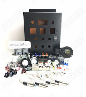
But...then I was attacked by the Google Marketing AI. You see, it had seen the searches I'd done watching others build their panels. And I was amazed at how the art had matured. And the youtube videos I'd watched had been logged by "The Man". And soon enough, suddenly I had adds popping up in every browser window for a Brew Buddy II 50A HERMS system from Auber Instruments. DIY kit was only $950 with free shipping and it had all the foundations of being closer to some of the enhancements I really wanted compared to many of the other systems (pre-drilled holes and some integrated lighted switches)... Drat... Damn you amazing AI!!! Well played. Well played...
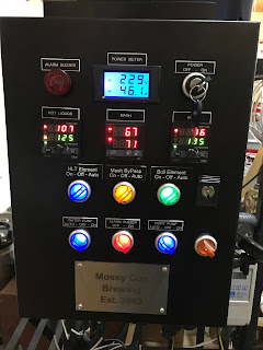
Well, the wheels started turning, and I basically dove in. The first thing I needed was to understand the exact datasheets for the PID's and the switches. Because I already knew I wanted to change some things on the function, but I really didn't relish the idea of drilling/punching more holes. That's why this setup was almost perfect. Ok, from the photo below, you can already see I drilled another control switch (Aux 120V) and I drilled another hole for a 3 prong output for controlling my HERMs Asco by-pass solenoids (either in full manual or in Auto based on the Mash temp settings).
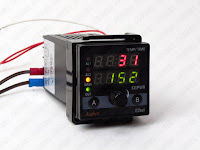
Reviewing the manuals before buying, it was obvious that the PID's included are nice, but quite a bit of overkill for how I brew. But it did present some nice options (like the quick twist dial to make changes to time and temp on the fly and not have to press up/down arrow a million times). The PID also has lots of options for step temps (on the HLT) and for hop additions on the boil, as well as a PERCENTAGE output for boils (since you can't really run boils in a temp controller feed back as the temp is a function of density-altitude for boiling and most eBrew setups quickly realize you just need to set it to a pulse modulated percentage duty cycle output to keep it a whatever boil you need for the size of your boil volume and losses Typically, for 15 gallons, that seems to be about 1500W (or 30% of my 5500W system)...we will see.
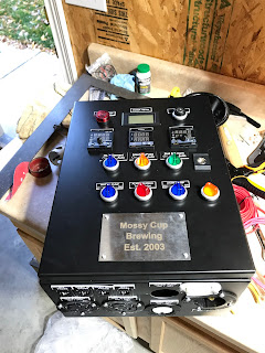
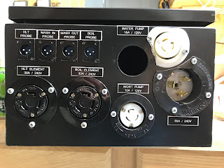
By carefully buying some additional 3-way switches and getting some of the new ones that had integrated lighting, I could save some spots that the classic Brew Buddy II used for just dedicated lighting indicators. And, it felt more "natural" to me to have the switch light up based on the action/output rather than some other disjointed light to "associate" with the action/switch. Here you can see the the extra 3-prong in white, that I drilled in to control the by-pass solenoids (basically GND is the neutral and each of the other legs is a 120V hot for that solenoid...so, even if you plugged something in that was pure power, it would be fine).
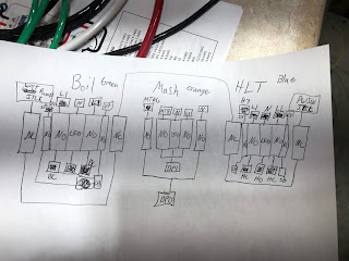
So, for customizations. The DIY already includes a pretty good diagram of wiring everything up, and there is a LOT. You also have to understand what they are doing with the lockout NC switch blocks and also realize that they have no "high power" needs on the front panel, so that makes it all nice low gauge wiring back to the DIN relays and high power main body. Also, the PID SSR control supplies low voltage (12-30v) control, not 120v, so I was going to need to put in a 120v AC to 12v DC supply to allow me to switch to full manual on the SSR's or I would need to double the 30A relays in the main box and bypass the SSR's, completely (a better solution, but not practical for the space I had). First, I eliminated the simple Off/Auto of the HLT and BK, and made it On-Off-Auto with lighting indicated based on if the element was ACTUALLY heating (meaning the light shuts off in Auto if the SSR isn't outputing voltage...same goes even in full manual "ON" mode if something is broken on wiring or the SSR).
Next I combined the warning light and the warning switch and put in a 3-way HERMS by-pass control to manage the Asco solenoids in my setup (this replaced ONE of the Ranco temp controllers). De-Energized, both solenoids are open to allow drainage/cleaning. In By-pass ON, the leg going into the coil is energized and is closed and the bypass leg is open. In By-pass OFF, the by-pass leg solenoid is energized and closed, and the leg going to the coil is open allowing heating (maybe a bit backwards and I should have made the tags say Heating or something for when the light is on, it is BY-PASSED). Ah well, what are you going to do.
Finally, I added an AUX 120v lighted switch and drilled a hole on the bottom right side for a sealable 3-prong 120v outlet (vacuum or third pump or just charger for my iPhone).
Full lock out of the panel turning on for both ON and Auto positions of the BK and HLT were added in (this required quite a few more NC switch block stacks).




No comments:
Post a Comment